Micro Broadcaster Community Radio Station broadcasting music 24/7
Micro power and range as permitted by FCC Part 15 rules with a coverage area of 1 mile. Programming includes random play of most genres and syndicated programs.
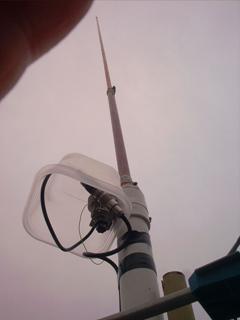
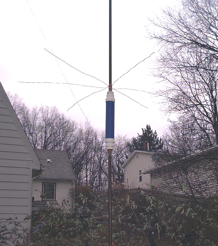
Recently I decided to try a different antenna system. My previous antenna is a 3 meter copper pipe with an L network at the base for tuning. The L network consists of a 100 uH choke from Radio Shack in series with the hot lead to the copper pipe. An air variable tuning capacitor is between ground and the junction of the copper pipe and choke. It tunes up at my frequency, 1500 kHz, and with no real ground radial system covers a .4 mile radius quite well. Shown at right is the antenna looking up from the base. The L network is in the plastic bin at the base. PVC pipe was used at the base.
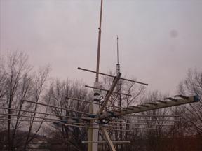
Not the ideal setup, the antenna is attached to the TV antenna mast. The TV antenna probably serves as part of the ground radial system. Surprisingly, no TVI problems.
Although, the signal does get into some of my telephones and the baby monitor so I decided to get it off the house. Dropping it to ground level, I knew I d need a more efficient antenna system. So after extensive reading from the ARRL handbook and all the posts on Part15.us, I decided to cook up another antenna. I figured my biggest loss was probably the 100 uH choke due to the wire size. That meant winding my own loading coil.
Rather than re-invent the wheel, I look at what s already out there working. I knew about what the coil inductance had to be so checking the B & W website (they make Mini-Ductor) the dimensions and wire size of the coil could be approximated based on their pre-made coils. I could have bought one from them for $40 but where s the fun in that.
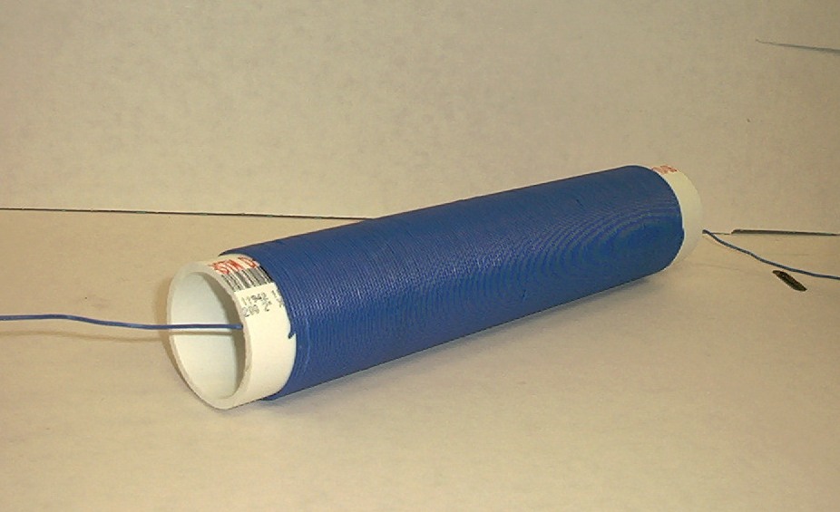
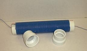
Based on the coil length and number of turns, I decided it would take about 100 feet of #18 solid wire. I had a spool of 3 conductor thermostat wire so the outer cloth jacket was stripped and the wires separated. I actually got blisters from stripping the jacket off. Anyway, 100 feet of wire was tight wound on the piece of 2 inch PVC pipe. A small hole just big enough to stick the wire through was drilled in one end and the winding was started. When the end of the wire was reached, another hole was drilled and the wire pushed through and pulled tight to keep the coil from slacking.
The pipe was cut, leaving about 1 inch on each end. This allowed gluing a 2 inch to 1.5 inch reducer on each end right up to the coil to help keep it from spreading out. The reducers were needed as I was going to insert an adapter on each end to receive a 3/4 inch male copper pipe thread. I couldn t find an adapter that would fit into the 2 inch pipe hence the reducers were used as 1.5 inch to 3/4 inch pipe adapters were available.
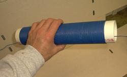
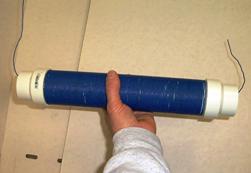
So, here s the coil with the reducers glued onto each end. Note I measured correctly as the reducers are snug against the coil. About 8 inches of wire was left on each end to allow connecting to the copper pipe. OK, so how s that happen
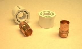
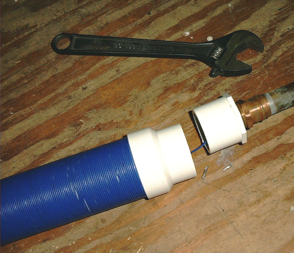
All this stuff is common plumbing parts from Home Depot. The PVC pieces will glue into the reducers on each end of the coil.The copper pipe adapters are soldered to the copper pipe first. The next picture shows how it goes together.
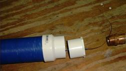
After the pipe adapter is soldered to the pipe, slip the PVC adapter over the coil pigtail. Strip the wire and cut it just long enough to allow safe working distance between the heat source and PVC. Pushing the PVC adapter slightly into the PVC reducer is OK. Just make sure you can pull it back out to allow gluing. After the pigtail has been soldered and the pipe cools, screw the PVC to the pipe by turning the PVC so as not to twist the wire off.
After you have both ends soldered and screwed together, it s a good idea to check for continuity to make sure the wire didn t break off either end. If you have a meter great! If not, a battery and light bulb will do.
I used a wrench to hold the copper pipe still and turned the PVC by hand. I didn t bother with sealing tape on the threads but it couldn t hurt. Another wrench for the PVC would have helped but I managed to screw it on far enough by hand.Make sure the copper pipe doesn t turn while you do this. If you break the wire off, well let s just say it would add some frustration to the project.
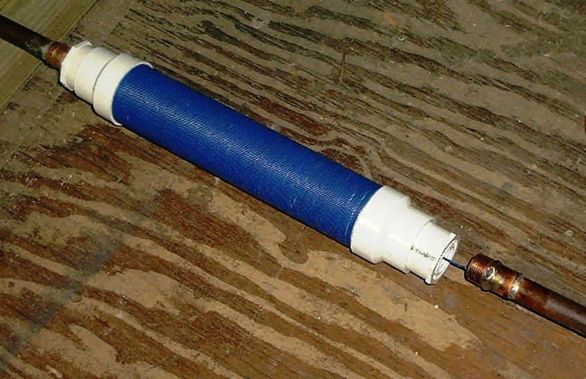
Wha-La! Home made loading coil as an integral part of a center loaded antenna. The same basic process could be used to make a base loaded antenna but I thought I d be different.
One thing about center loading, you need just a bit more inductance than a base loaded antenna (more turns on the coil.)
My copper pipe was from another antenna I already had. The coil ended up slightly below center.
The over-all length with the coil is about 10 foot 6 inches. The coil itself is about 16 inches so the actual radiator is under the 3 meter limit. I figure if they don t count the coil, I m OK.
The bottom of the antenna has another 3/4 inch pipe adapter which screws into the appropriate PVC adapter which insulates the antenna from the metal box it s attached to.
The box at the base was a surplus traffic signal box. Just the right size for a small transmitter like the Spitfire.
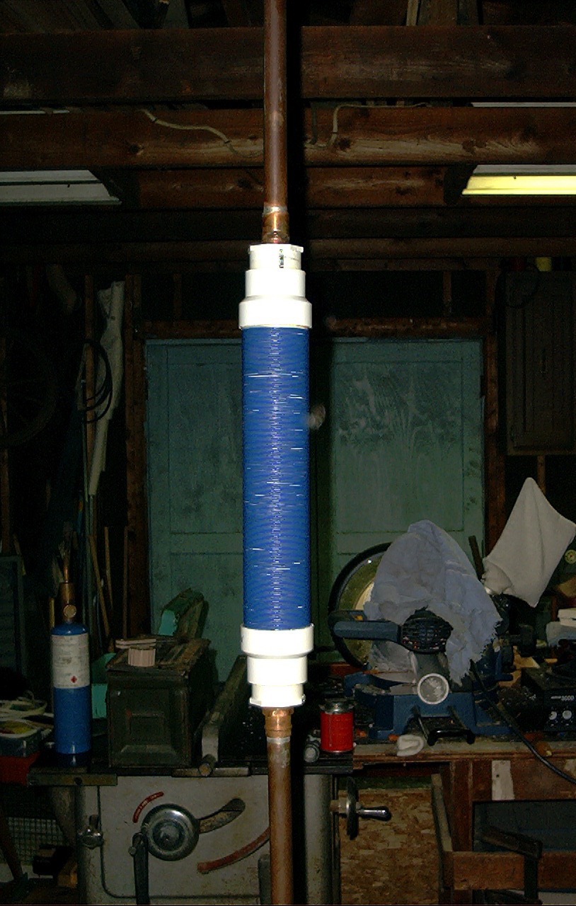
Since I forgot that center loaded antennas need a bit more inductance, my by-guess-by-golly method tuned up at about 1700 kHz, just a little high.
To take care of tuning the antenna to 1500 kHz, I could have made the top section adjustable in length. In fact the used piece of copper from an old antenna was originally adjustable but more or less permanently set.
So (note wires at top of coil) a capacity hat was used to lower the frequency of the antenna.
How s that work If you increase the inductance by lengthening the antenna or adding more coil the frequency comes down.
Likewise, if you increase the capacitance of the antenna by increasing the surface area of the radiator the frequency comes down also.
The capacity hat was added and is pruned to tune the antenna. Since the antenna is already at the limit for length, this worked great! Once the tuning is good, the wires will be soldered to the antenna.
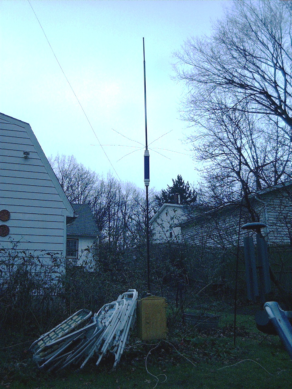
Well, there it is! A thing of beauty in the eye of the beholder. Note the (white wire laying on the ground) extensive ground radial system. Well, it was cold out so perhaps in the spring I ll improve on that. Maybe those lawn chairs leaning on the box really help. Anyway, the hardest part was stripping 100 feet of jacket off the wire for the coil. But if I can save a buck, what should I care about a few blisters.
On the plus side, the antenna works better than the one on the roof.